All-Terrain MobilizerⓇ
Introduction
Current challenges in the marketplace and new applications have motivated CM Automotive System Inc. to redesign its CTI system. This new effort will provide a wheel valve to improve the warfighter’s survival when operating a vehicle in the combat zone. The wheel valve isolation feature will shut down and isolate a flat tire for inflation and deflation. The warfighter can then inflate the remaining tires to the survival tire pressure for escape.
Similar design modifications are needed to include other applications. Such applications provide for driving through rivers or saltwater exposure. The manifold and the wheel valve require water-tight assemblies and internal treatment of all surfaces.
In a similar application for a 4×4 vehicle, the dash did not have enough room to mount the CTI controller. We replaced our standard controller with a newly designed eight-button switch-pack controller, at approximately half the size.
Moreover, these operating buttons on the switch-pack are large: .908″ x.908″ and, therefore, can be activated from the cab with the warfighter using arctic gloves. The switch-pack controller is compact, lightweight, and has multiple built-in LEDs for each button, indicating the position.
System Description
The CTI system consists of switch-pack activated Controller, Power Manifold, Interconnecting Harness and Wheel Valves; one per wheel. When the system is powered up, the Controller waits to receive the Terrain setting from the driver. When this input is received, the Controller signals Power Manifold to start the automatic CTI cycle.
The Transducer first measures the current tire pressure and compares the same to the desired terrain tire pressure. If the desired pressure is higher, the power Manifold switches to the inflation mode. However, if the desired pressure is lower, the power Manifold switches to the deflation mode.
When the desired tire pressure is reached (as measured by a Transducer), the manifold Quick Exhaust Valve (QEV) opens and shuts down the system as evidenced by a blast of air exhausting through the QEV. The accelerated deflation through the QEV and normal deflation through each control orifice in the wheel valve create an imbalance of pressure around the wheel valve piston and cause all valves to close terminating the CTI cycle.
The other two Valves, Inflation & deflation, are designated as INFV and DEFV. During the deflation mode the DEFV also has a built in orifice in the exhaust port to create a back pressure otherwise it has the same function as the QEV, i.e. the system will try to shut off. The DEFV orifice is calculated and tested to assure that the deflation valve remains open and does not pre-close throughout the complete range of pressure adjustments.
Standard Configuration
There are four standard Terrain Settings: Highway; Cross Country; Mud, Sand & Snow; and Emergency. Should you require any additional settings such as Kneeling position, to facilitate transport height or wheel loading, please consult factory.
The individual sub-assemblies that provide the above tire pressure settings are described as follows:
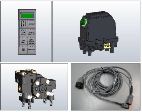
SWITCH-PACK CONTROLLER
This Controller is of a digital design and interfaces with two PCB’s, one each located in the switch-pack and the cover of the manifold. The PCB located in the switch-pack drives and controls the input while the PCB in the manifold activates the manifold to start the CTI operation. The results of the automatic operation are displayed on the numeric display. The controller operates on 5 VOLTS after the original 24 VOLTS supply has been reduced and conditioned.
MULTIPLE CHANNEL SYSTEM
The CTI system from CM Automotive is available as a single or a dual channel system. Single channel means that all tires are connected to the same channel. Dual channel systems allow two selected groups of tires, each connected to a dedicated channel. Additional multiple channel systems are not popular and, as a consequence, we do not have these in 3 production. However, up to a four channel configuration can be produced but it is cost effective only on large quantity programs. Please consult the factory.
OVER SPEED CONTROL
For tire safety a speed control is necessary. As the vehicle speed increases over and above the set point for a given tire pressure and for one minute time period, an amber light will start blinking on the controller, indicative of the higher speed. When the one minute time period is exceeded, the CTI system is activated to inflate the tire to the next higher setting and lowering the vehicle speed has no effect. After the tires have been inflated to the next higher setting the vehicle speed can be lowered and the controller reset to deflate the tire to a lower pressure setting.
TIRE PRESSURE MEASUREMENT
The pressure transducer selected for our CTI system is a name brand from Texas Instrument. This company has been resold after relocating. For the last 30 years and under new ownership, we have had the same reliability and performance from the product. The transducer has the measuring range of 150 psi. Software provides tire pressure calculations to include temperature compensation. Such measurement improves the overall accuracy of the adjusted tire pressure.
PRIORITY PRESSURE SWITCH
As the name suggests, the pressure switch provides for the priority of air to be supplied to the brakes. When the CTI system is in full operation and other devices like windshield wipers and brakes are also operating, the heavy consumption of air may lower the air supply pressure. When uninterrupted, the air supply pressure could dip below the minimum operating pressure for the brakes. The priority pressure switch is set to stop CTI operation at 94 psi, maintaining the balance of air pressure in reserve for the vehicle brake operation.
BLACKOUT MODE
The CTI Controller works with two separate electronic circuits; LED’s and power circuit, and both circuits can be switched off independently. Therefore, the LED lighting can be turned off while the power circuit continues to operate the CTI system. For a hardware connection, the CTI controller provides a single wire that the customer can integrate in to a vehicle blackout mode switch to turn off the LED lamps of the CTI system.
LOW AIR INTERRUPT
As noted in the description of the priority pressure switch above, during the decreasing pressure mode the pressure switch trips out at 94 psi. This is also known as the “low air interrupt” that also shuts off the CTI system. As the compressor runs, the air supply pressure continues to build up. When the pressure reaches 115 psi, the pressure switch closes and reactivates the CTI system. The tire pressure will start building up from where it left off when the low air interrupt occurred.
Such interruptions can be a consequence of a low output air compressor. On a 6×6 vehicle I have noticed 8 interruptions from emergency to highway increasing the inflation time to 40 minutes. The compressor size was 10 cubic feet per minute against the recommended size of 15 cubic feet per minute. An adjustment of the inflation valve orifice to lower flow allowed no interruption and lowered the inflation time to 20 minutes. Please call the factory for help should you find yourself in the above situation.
AUTO TIRE PRESSURE RECHECK & ADJUST
The CTI controller provides a periodic check of the tire pressure. An adjustable timer on board is available from 30 minutes to 60 minutes to activate the CTI cycle. Upon recheck, all tires are opened to the manifold so the transducer can measure the tire pressure. If the measurement falls within the tolerance of the last adjusted tire pressure, the system shuts off. If not, the tire pressure is adjusted to the last tire pressure setting, the CTI system shuts off and the timer resets.
NUMERIC DISPLAY
The switch-pack controller houses a digital display that provides CTI operational information to the driver. During the tire pressure adjustment process the actual tire pressure is displayed in two digits, increasing for inflation or decreasing for deflation along with the location of tires; front or rear. The second line also displays the title of the process like,Tire pressure adjustment.
Optional Configurations
LOAD SELECT
This provision allows the option to have a switch marked with three selectable LED positions representing full load, half load and empty. In conjunction with the terrain settings (total of 4) and the three load positions, 5 a total of 12 settings are provided for a finer combination of load and terrain. Running the vehicle over 12 settings will enhance the vehicle mobility representing optimized values. This provision requires that the customer provide all the details of the twelve tire pressure settings.
ACCELERATED DEFLATION
The minimum requirements are: 187” dia. (4.75 mm) wheel valve orifice, a .356” dia. (9.00 mm) air passage in each hub, and a .312 dia. (8.00 mm) deflation orifice.
Prior to the assembly, check the air passage size in each hub. Plumb the system with ½” (13 mm) hose lines each not to exceed 10 feet in length. The hoses need to be laid out from the manifold to the axle crossing and turned parallel to the axle with a 3” radius to meet the hub inlet air fitting without any kinks. Utilize only brass fittings for air service. Minimize any elbow and tee fittings. Should you require any help, please call factory for assistance.
Specification
Single channel
Dual Channel
24VDC 54 WATT CURRENT 1.35 A
24VDC 68 WATT CURRENT 1.25 A
Pressure switch
94 psi 115 psi Decreasing. Increasing
Transducer Range
0-150 psi – .5V TO + 4.5 V
Solenoids
24VDC 10W, 22W. CL – “H”
Manifold
IP 68 & 69 (dust proof, submersible in fresh or salt water to a depth of 2.O meters and high pressure, hot water spray proof)
Wheel Valve &
IP 68 & 69 (dust proof, submersible in fresh or salt water to a depth of 2.O meters and high pressure, hot water spray proof)
Run Flat
Not needed, wheel valve isolates for flat tire conditions
Environmental Tests
Durability: Cycling at ambient temperature from -50F to +140F
Electrical Susceptibility and Emissions per MIL STD-461D and 462D
Relative humidity per MIL STD-810
Vibration per MIL STD-810E
Steam Clean and Pressure Wash per SAE J 1544
Various electrical system tests per MIL STD-1275A
Customer
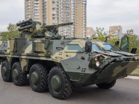
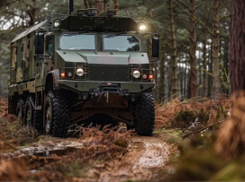
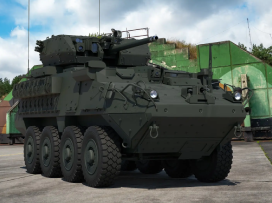
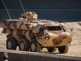
To date CM Automotive has supplied over 30,000 CTI Systems to the military and civilian truck markets. Listed below are many of the customers and vehicles using CM Automotive All Terrain Mobilizer:
ALVIS VEHICLES (England) PIRANHA 2
AMERICAN GENERAL (USA) M35A 4×4 HMMWV 4×4
ARMET (Canada) FORD 350
ASHOK LEYLAND (India) HMV 6×6 & 8×8
BAE (South Africa) RG-32M 4×4
BERING TRUCK (USA) 4×4
DOOSAN (ROK) DUV 6×6 TARANTULA 6×6
E- ONE (USA) FIRE TRUCKS
FNSS (Turkey) AMPHIBIOUS ASSUALT BRIDGE 8X8
FNSS (Turkey) PARS 8×8
GDLS (USA, Canada) LAV 8×8
GD-OTS (USA) GROWLER 4×4 FLYER ITV 4×4
GPV (USA) 6×6
HYUNDAI ROTEM (ROK) WAV 8×8
LIGHT RACING (USA) JAMMA 4×4
NUROL MAKINA (Turkey) 6×6
OSHKOSH DEFENSE (USA) HEMTT 8×8
HET 8×8
PLS 10×10
PATRIA (Finland) AMV 8×8
SHINJEONG (ROK) MDAP 4×4
ST KINETICS (Singapore) TERREX 8×8
TIMONEY (Ireland) CLOUD LEOPARD 8×8
OHIO 8×8
THALES (Australia) BUSHMASTER 4×4
UROVESA (Spain) LKAD 4×4
VAMTAC 4×4
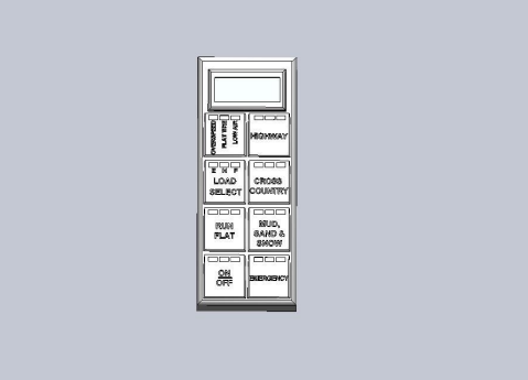
CAN BUS SWITCHPACK
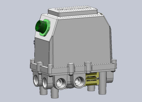
WATERTIGHT SINGLE CHANNEL MANIFOLD
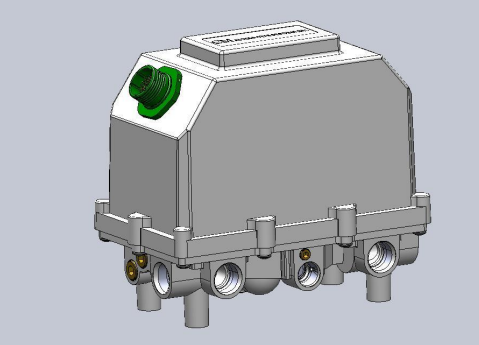
WATERTIGHT DUAL CHANNEL MANIFOLD
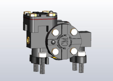
ISOLATION DIRECT MOUNT WHEEL VALVE
V E H I C L E S